5/30/12
When we arrived in lab, we assembled our gears into the Lego transmission housing. When we were assembling the gears, some gears were not meshing correctly, and some gears were placed incorrectly on the shafts. We have sent new .STL files for reprinting and we should have them done by Friday. We are unable to test what we have now because of the incorrect gear meshing. Once the new pieces are printed, all gears (1, 2, 3, 4) will be able to run correctly. We hope that first gear will have the most torque and that fourth gear will have the highest RPM.
Despite the conflicts between our gears and shafts, we still managed a way to perform some testing.
We measured the RPMs:
First gear: 36 RPMs
Second gear: 124 RPMs
Third gear: 440 RPMs
Fourth gear: 536 RPMs
We also measured the torque of first gear:
The maximum grams that could be lifted was 400 grams.
Using this information, the experimental ratios are very close to our theoretical ratios.
Wednesday, May 30, 2012
Wednesday, May 23, 2012
Week 8 Summary
5/23/12
Over the weekend, we completed the final assembly and mechanism of our manual transmission.
When we arrived at lab, we received multiple gears that were printed from the 3D printer. We had to wait an additional 30 minutes for the rest of our project to be printed. Once everything was printed, we decided to piece everything together into the gear box housing that Deepak has made for all manual transmission projects.


When we pieced everything together, we ran into minor problems. When we meshed all gears together, the gears would push against each other which would cause stress against other gears and shafts. We decided to to use very fine sand paper to fix these problems and to reprint just two gears to fix our assembly.
Wednesday, May 16, 2012
Week 7 Summary
5/20/12
Today the entire assembly of our manual transmission has been pieced together in Pro ENGINEER. What is left to do is to set up the mechanics and animations for it.


5/16/12
Today every gear and axle has been made on Pro ENGINEER. We are now creating an assembly which will show the mechanics of our manual transmission. The one thing we need to figure out is the spacing between each and every gear on each axle. It is important that the spacing is perfect because gears could mesh poorly and strip the gears. Here is a picture of our general assembly:

After spacing has been determined, we will send Deepak the STL files for printing.
Deepak has showed us how to make a Mechanism on Pro E. By next week, he wants the entire transmission as a Mechanism on Pro E.
Today the entire assembly of our manual transmission has been pieced together in Pro ENGINEER. What is left to do is to set up the mechanics and animations for it.

Finished assembly

Exploded assembly
5/16/12
Today every gear and axle has been made on Pro ENGINEER. We are now creating an assembly which will show the mechanics of our manual transmission. The one thing we need to figure out is the spacing between each and every gear on each axle. It is important that the spacing is perfect because gears could mesh poorly and strip the gears. Here is a picture of our general assembly:

Input Shaft (Green), Output Shaft (Blue), Shifter (Gray)
After spacing has been determined, we will send Deepak the STL files for printing.
Deepak has showed us how to make a Mechanism on Pro E. By next week, he wants the entire transmission as a Mechanism on Pro E.
Wednesday, May 9, 2012
Week 6 Summary
5/9/12
Today in lab, we have gone over our results with the stress analysis. A myriad of gears were tested to show the strength in the teeth. These results will be used for more modifications to ensure the highest quality in our prototype.
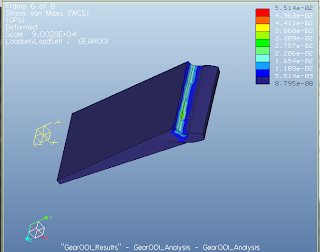
After the analysis, the part will show points that are being under the most stress. A way to fix this is to add rounds that connect the teeth to the base of the gear itself. This will add extra support which can make the gear run under even more force when needed. This will greatly enhance the performance.

After the analysis, the part will show points that are being under the most stress. A way to fix this is to add rounds that connect the teeth to the base of the gear itself. This will add extra support which can make the gear run under even more force when needed. This will greatly enhance the performance.
Wednesday, May 2, 2012
Week 5 Summary
5/5/12
After all the calculations for the gears, the information was condensed into a spreadsheet. Each person in the group is assigned to draw certain gears. In the end, all gears will be drawn and ready to print.
Here is a picture of 1 of the 18 gears needed for our system:

5/2/12
Today in lab, Deepak has showed us applications in Pro Engineer. The application he focused on was Mechanica. In Mechanica, Deepak used a sample gear tooth to demonstrate how to perform a myriad of stress analysis in order to determine if the design will hold up for the manual transmission. He has also told us about his updated Dropbox. It now contains his sample gear, updated rubric, and tutorials on how to use Mechanica and stress analysis.
We also asked Deepak for help for drawing the gears. Each of us are having trouble with this step. We need to have all of our gears drawn soon because the .STL files are going to be due very soon for printing.
Subscribe to:
Posts (Atom)